Juan Beaver (jcb259), Mikala Goodloe (mtg73)
Pre-lab is attached to the end of the document. Code for this lab has been submitted to Canvas.
Report Sheet Questions:
1:
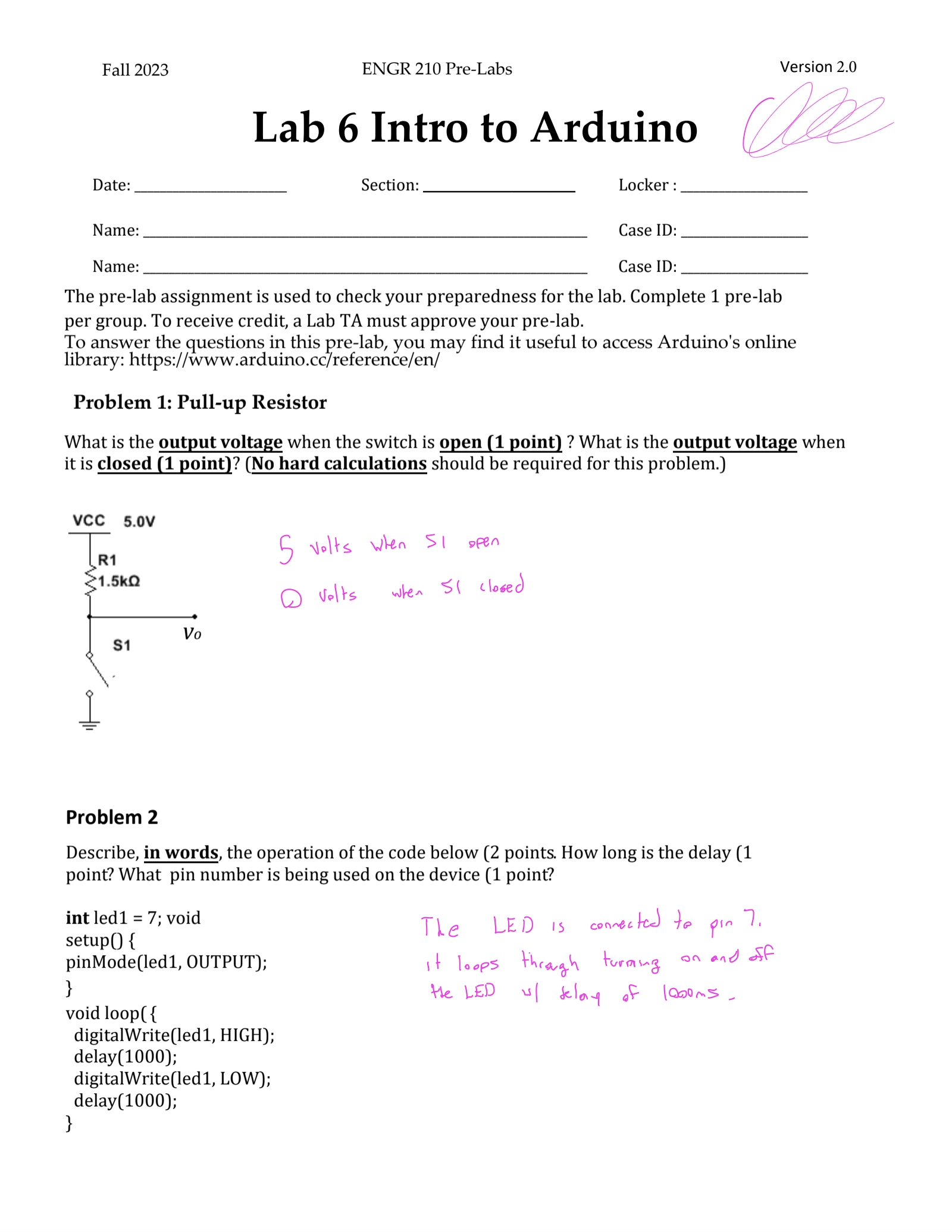
In the pre lab, you were introduced to the operation of a pull-up resistor. You then used a pull-up resistor in the lab as an input for your chaser. Could a resistor value lower than the one used in the lab work as a pull-up resistor? What about a higher value? Which would you choose and why?
A pull-up resistor of a lower value could still work but it can cause issues by using a lot of power when the circuit is closed. A higher resistance value would make it harder to verify the state of the switch as the current would be very small. I would probably choose to go with a slightly higher resistance value as it would be more efficient when the circuit is closed.
2:
Using your understanding of a pull-up resistor with a switch, draw a pull-down resistor with a switch that uses a resistor value of 1.5 kΩ.

3:
Explain how a pulldown resistor would work.
A pulldown resistor works by ensuring that a wire is pulled to a ground state, or logic low (0), when it’s not being actively driven by anything else. This is done by connecting a resistor between the wire and ground. In digital circuits, a floating signal could switch between high or low states due to electrical noise in the system. This could potentially lead to unpredictable behavior or incorrect readings. By using a pulldown resistor, the line will always be pulled to a known state (low) unless it’s being actively driven high by connected equipment.
4:
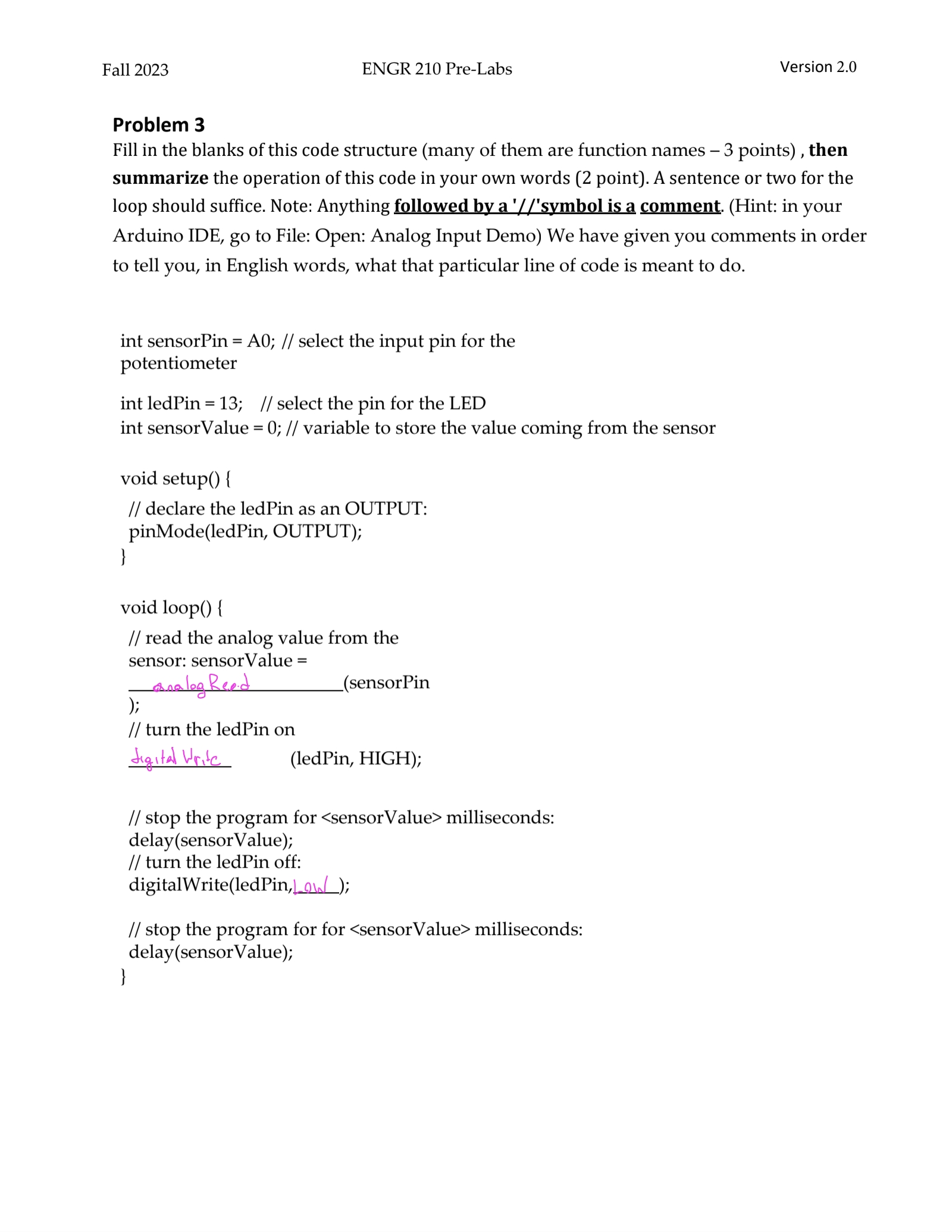
In Part 4 of the lab you used an analog pin. The incoming voltage is assigned a value between 0 and 1023. Why do you think the range of values is exactly 1024?
The range of values is exactly 1024 because the Arduino uses a 10-bit analog to digital converter (ADC). This means it can represent the analog value with 1024 digital levels (2^10 = 1024), which ranges from 0 to 1023.
Prelab:
Code:
Part 2:
int led1 = 2;
int time_delay=200
void setup() {
pinMode(LED1, OUTPUT); // Initialize the digital pin as output
}
void loop() {
digitalWrite(LED1, HIGH);
delay(time_delay);
digitalWrite(LED1, LOW);
delay(time_delay);
}
Part 3:
int led1 = 2;
int led2 = 4;
int led3 = 6;
int input_pin = 9;
void setup() {
  pinMode(led1, OUTPUT);
  pinMode(led2, OUTPUT);
  pinMode(led3, OUTPUT);
  pinMode(input_pin, INPUT);
}
// the loop function runs over and over again forever
void loop() {
  int input_pin_value = digitalRead(input_pin);
  if (input_pin_value == HIGH){
    digitalWrite(led1, HIGH);  // turn the LED on (HIGH is the voltage level)
    delay(200);                      // wait for a second
    digitalWrite(led1, LOW);
    digitalWrite(led2, HIGH);   // turn the LED off by making the voltage LOW
    delay(200);
    digitalWrite(led2, LOW);
    digitalWrite(led3, HIGH);
    delay(200);                      // wait for a second
    digitalWrite(led3, LOW);
    digitalWrite(led1, HIGH);
    delay(200);
  }
  if(input_pin_value == LOW){
    digitalWrite(led3, HIGH);  // turn the LED on (HIGH is the voltage level)
    delay(200);                      // wait for a second
    digitalWrite(led3, LOW);
    digitalWrite(led2, HIGH);   // turn the LED off by making the voltage LOW
    delay(200);
    digitalWrite(led2, LOW);
    digitalWrite(led1, HIGH);
    delay(200);                      // wait for a second
    digitalWrite(led1, LOW);
    digitalWrite(led3, HIGH);
    delay(200);
  }
}
Part 4:
int led1 = 2;
int led2 = 4;
int led3 = 6;
int input_pin = 9;
void setup() {
  pinMode(led1, OUTPUT);
  pinMode(led2, OUTPUT);
  pinMode(led3, OUTPUT);
  pinMode(input_pin, INPUT);
}
// the loop function runs over and over again forever
void loop() {
  int input_pin_value = digitalRead(input_pin);
  int input_delay = analogRead(A4);
  if (input_pin_value == HIGH){
    digitalWrite(led1, HIGH);  // turn the LED on (HIGH is the voltage level)
    delay(input_delay);                      // wait for a second
    digitalWrite(led1, LOW);
    digitalWrite(led2, HIGH);   // turn the LED off by making the voltage LOW
    delay(input_delay);
    digitalWrite(led2, LOW);
    digitalWrite(led3, HIGH);
    delay(input_delay);                      // wait for a second
    digitalWrite(led3, LOW);
    digitalWrite(led1, HIGH);
    delay(input_delay);
  }
  if(input_pin_value == LOW){
    digitalWrite(led3, HIGH);  // turn the LED on (HIGH is the voltage level)
    delay(input_delay);                      // wait for a second
    digitalWrite(led3, LOW);
    digitalWrite(led2, HIGH);   // turn the LED off by making the voltage LOW
    delay(input_delay);
    digitalWrite(led2, LOW);
    digitalWrite(led1, HIGH);
    delay(input_delay);                      // wait for a second
    digitalWrite(led1, LOW);
    digitalWrite(led3, HIGH);
    delay(input_delay);
  }
}